Yet Another Brewery Build

The Homebrew Forum

Help Support The Homebrew Forum:

This site may earn a commission from merchant affiliate links, including eBay, Amazon, and others.
hmm... and there's me thinking wiring the STC-1000 was complicated... :oops:

loving the build pics mate. Nice set up :thumb:
 
evanvine said:
Were 2 x 20A SSRs cheaper than 1 x 40A SSR + only half the wiring?

Nope! It was the way I planned and implemented it, but in retrospect, using a single SSR to drive both output sockets would have been fine for my needs. A single 20A SSR would do the job, as both output sockets are fused to 10A and the elements draw around 8-9A each in practice. My original thinking was two SSRs would let me switch the elements on and off as I pleased, but just switching the output of single SSR would acheive this.

There are some minor benefits - the problem of thermal disipation is spread across two SSRs instead of one. And in the future I may replace the PID with my own microprocessor, so I have a bit more flexibility in that case.
 
MacKiwi said:
Here's the schematic...

pid.jpg


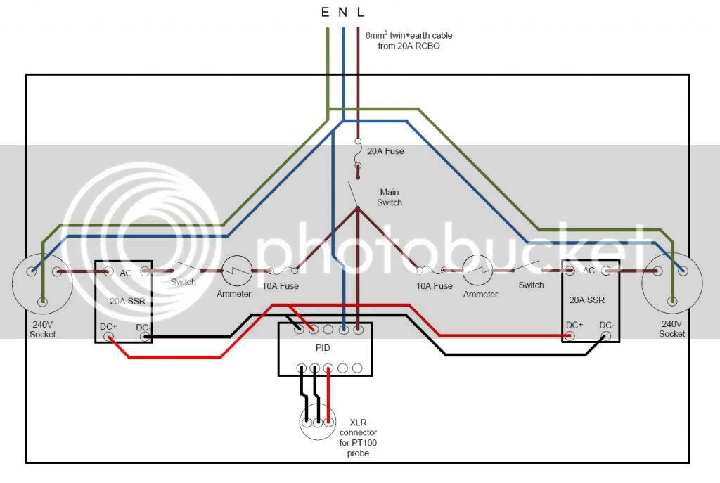
A lot of the switches, and certainly the ammeters, you can do without. The 20A fuse is redundant, as there is a 20A RCBO at the other end of the cable. But I would definitly keep the 10A fuses.
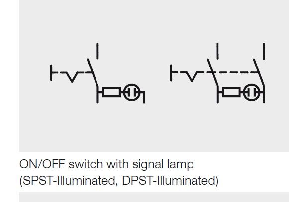
Thanks for the schematic, MK, very helpful. Cheers
 
how are those neon switches wired up?
I got some from maplin (dpst switches) and cant for the life of me figure them out.
There is 4 terminals.... and it needs a neutral as its got a neon that lights up, but im not sure other than that !
Any advice appreciated.
 
mhewitson said:
how are those neon switches wired up?
I got some from maplin (dpst switches) and cant for the life of me figure them out.
There is 4 terminals.... and it needs a neutral as its got a neon that lights up, but im not sure other than that !
Any advice appreciated.

Yeah, that caught me out at the start too :D

So there is a neon lamp (high resistance) across the switch pairs. I'll try and dig out a schematic I found when I'm back in the office tomorrow. But from memory, I used one half of the DPST switch as a regular switch (live in on one side, switched live out on the other), and on one of the 2 unused terminals I connected neutral. Depending on which of the two you use, the light will either always be on, or on when the switch is on (I think).
 
This is all I could find on the switches....

switch.jpg


The DPST is on the right. You can see the lamp is between the two bottom terminals. So if you are using the top left terminal as live-in, and bottom left as switched live out, then connectoing the bottom right terminal to neutral will result in the switch illuminating when switched on.

Clearly you can't use the other half of the switch to switch live in this case.
 
Many thanks, I'll give that a shot! Iv already blown a couple of fuses and a ssr wiring it up wrong :s and I consider myself good with electricity!
 
Back
Top