solar pumps power

The Homebrew Forum

Help Support The Homebrew Forum:

This site may earn a commission from merchant affiliate links, including eBay, Amazon, and others.
Ok, some info for people considering how to power their solar pump...

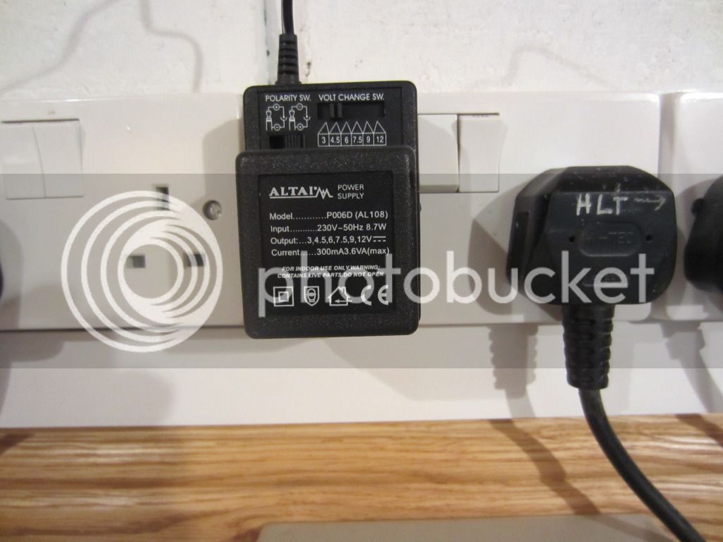
I bought a variable voltage power supply home from the office and had a play. Here are my (rough and ready) results...

12V : The pump shifted 8l/min of water in my test setup. Amps used was roughly in line with pump wattage.
7V : A rough mid-point between 12V and 3.4V. 5l/min shifted, so it appears roughly linear.
3.4V : This was the lowest voltage that the pump still operated at. It shifted 2.5l/min.
3.3-0V : pump is dead, no water shifted.

So the pump gives a (roughly) linear response of 2.5-8l/min between 3.4V and 12V (if I had more timed I'd take more sample points).
For me, the key result is that the minimum flow of the pump when using voltage control is 2.5l/min. I had hoped to go down to 1l/min when sparging, but clearly this isn't going to happen. Bummer.

I went back to my (possibly dodgy) PWM controller, Results are...
On : 8l/min.
Min : 6l/min (!!!)

Below "min" the pump wouldn't shift anything. So the range supported by my PWM is 6-8l/min, which is not worth the bother of fiddling with the PWM. I'm going to take the PWM controller into the office and monitor the output with a scope to see if it really is duff. Will post back with the results...

Mark1964's bypass valve is starting to look like a good solution...
 
MacKiwi said:
I'm going to take the PWM controller into the office and monitor the output with a scope to see if it really is duff. Will post back with the results...

Will be interesting to know what you find. I don't have one of these solar pumps so don't know what sort of motor it is or what if any electronics is inside the motor case but usually PWM control would give good speed control from very slow through to fast - i.e. you get a smooth transition. I made a PWM control for a model train once and the control of speed was very good. With voltage control you don't get much torque at lower voltages.
 
I use a Solar pump for various brew tasks (not sparging though, gravity fed) and got my power supply from Maplins. They might be cheaper on their Ebay shop.
 
Ok, here's what my cheap-as-chips PWM controller is doing...

(this one http://www.ebay.co.uk/itm/Led-Dimmer-12 ... 41626ed156)

Firstly, one of my problems is that there is a very, very narrow range between full-on and full-off. I wondered if this was due to some interaction between the motor and pwm output, but in fact it is just because the controller is naff. I observe the same behavior with the oscilliscope. In other words, although the dial turns ~300 degress on the controller, for ~290 degress of that the output is either fully on or fully off. I assume this is due to a duff PWM controller, as this is no use to anybody in any application, and that a half-decent 12V LED dimmer would behave better.

Second observation is that the output isn't really PWM. In the small range where I can observe an intermediate voltage, the voltage is, for all intents and purposes, static. If I look very closely I can see the pulse train, with a period of ~80ms, but an amplitude of only 20mV. This suggests to me that the controller has a large capacitance on the output, and the PWM pulses are just charging that up to a level. In other words, it is really behaving like a variable-voltage output, not a PWM output. And as per my post above, variable-voltage doesn't let me get down to the low flow-rates I am after.

So, in conclusion, PWM may still be the way forward. But I need to find/build a decent PWM controller - these cheap LED dimmers are pants.

(edit : this looks to be the real deal http://www.suntekstore.co.uk/product-14 ... _knob.html)
 
MacKiwi said:
If I look very closely I can see the pulse train, with a period of ~80ms, but an amplitude of only 20mV. This suggests to me that the controller has a large capacitance on the output, and the PWM pulses are just charging that up to a level. In other words, it is really behaving like a variable-voltage output, not a PWM output. And as per my post above, variable-voltage doesn't let me get down to the low flow-rates I am after.

Bear in mind that the motor will generate a back EMF due to collapsing flux so that may be confusing the issue somewhat. You'd get a better idea of what the PWM device is really doing if you connected a resistive load instead of the motor and then looked again with the scope.

Having said that, I am pretty sure based on what you have said that your PWM controller is stuffed :roll:
 
My test with the oscilliscope was just monitoring the output of the PWM directly (no load, aside from the scope probes). I agree that using a representative load would be better (maybe an LED light, that is what it is designed for), but I didn't have anything to hand (high-speed digital electronics lab, the only resistors I have laying around are in 0603 packages (ie: dust)).
 
MacKiwi said:
My test with the oscilliscope was just monitoring the output of the PWM directly (no load, aside from the scope probes). I agree that using a representative load would be better (maybe an LED light, that is what it is designed for), but I didn't have anything to hand (high-speed digital electronics lab

Ah - in that case, even a small capacitive load is likely to cause the effect you have seen. The PWM will not have a totem pole type output, only likely to be a single transistor pulling high or low so if there is no load, the output can float as you have seen - the 1MOhm scope input (assuming x1 probe) will not be enough to load it. Even a few kOhm would be enough load to see the real output :thumb:

MacKiwi said:
the only resistors I have laying around are in 0603 packages (ie: dust)).

I know what you mean there ;) - I try and stick with 0805 unless space is really tight :thumb:
 
tazuk said:

Can't say about the rest but I use the LED Dimmer on my stir plate and it's brilliant. :thumb:

This is what runs my solar pump. It looks weedy but I can pump 45l from my boiler to my HLT (which is approx 2m above it) in just over 15 minutes. It's slowest setting is too low but the next one is perfect for recirculating and could be used for sparging by restricting the flow to the pump using the ball valve.

IMG_0497.jpg
 
Sorry Tazuk, you ask a simple question, and...

If you go with your first two links (LED dimmer, 12V power supply) you will have exactly what I have now. The LED dimmer may even work better than mine. If you just want to move water/wort from A to B then it's great. But I have failed to control the flow down to 1l/min (for sparging) with this setup. You may have better luck, but I don't think it is certain.

If you use one of those variable/tattoo power supplies in your later links, then I don't think you gain a lot. My experiments show you can control the flow between 2.5-8l/min with these. They don't work if you want to go down to 1l/min.

I will continue investigating PWM options, so may be able to definitivly say if it works down to 1l/min or not soon, but the jury is still out for me.
 
orlando said:
Can't say about the rest but I use the LED Dimmer on my stir plate and it's brilliant. :thumb:

I really need to try a different PWM module - seems to work for everyone else :D
 
Coming back to this with new insight having investigated the pumps.

These solar pumps have "brushless" DC motors (BLDC). They have two wires to the outside which means they have internal electronics to perform the electronic commutation required.

The internal electronics are not likely to be happy with a supply that is continuously and rapidly turning on and off (i.e. a PWM signal). The PWM style "dimmer" control is unlikely to give anything like satisfactory results when it comes to speed control as MacKiwi has found (MacKiwi your PWM control may not be faulty at all).

Some BLDC motors have controllers which include a short startup delay when power is applied - these will definitely not work with a PWM controller because the controller is continuously performing the turn on delay.

If it was possible to access the three phase wires inside the motor then external electronic commutation could be used and then speed could be controlled very accurately.

The least worst option for trying to control the speed of a two wire BLDC motor is therefore voltage control.

A sort of voltage control could be fudged together with a PWM style controller if a large capacitor was hung on its output to average the PWM signal into a voltage proportional to the PWM rate. Usually if a PWM signal is used in this way, a bit more than a large capacitor would be used to smooth the PWM signal adequately.

Hope this helps :thumb:
 
Great info EskimoBob - thanks for that. You've saved me a lot more pissing around with PWM. As I've already determined that voltage control doesn't work for me (the pump stops running before the flow rate is low enough for fly sparging), I think that a bypass valve looks like the best solution in my case (feel free to say "I told you so", Mark1964)
 
told you so :tongue:

Consider reducing the pipe diameter to the spinny sparger it slows down the flow and at the same time builds up water pressure to spin it :thumb:
 
Back
Top