HLT HERMS - Servo control for Proportional Mixing.
None of this is relevant if you are looking at solenoid driven valves!
Please note - this does not include finished detailed circuits, it is a few ideas for those who know a bit of electronics. I have made something along these lines but have not fully tested or toleranced the design.
The easiest way to achieve a variable flow is with motorised valves - there are many examples including central heating.
The cheapest way to implement a motorised valve is with an off-the-shelf servo, typically used in Radio Controlled models. It contains the motor and gears at a fraction of the individual part cost.
The simplest way to control this servo is by removing part of the case and connecting directly to the motor. The drive from the PID makes the motor run in one direction for "hotter" and the other for "cooler" (some form of current limiting will be needed). However the method shown here does not involve taking the servo apart and would suit any similar servo with sufficient stall torque.
The outputs from a standard inexpensive eBay PID (TET612, N2006P) include a relay with normally open and normally closed contacts or a Solid State Relay drive of 8V open circuit and 40mA short circuit.
In this case I have chosen to use the SSR output. It can be set to have a maximum repetition rate of 2 seconds and the time it is "on" is determined by the heat requirement of the system.
This is not directly compatible with an off-the-shelf servo mechanism:
Taken from: http://en.wikipedia.org/wiki/Servomechanism -
"The servo expects a pulse every 20 ms in order to gain correct information about the angle. The width of the servo pulse dictates the range of the servo's angular motion.
A servo pulse of 1.5 ms width will typically set the servo to its "neutral" position or 45°, a pulse of 1.25 ms could set it to 0° and a pulse of 1.75 ms to 90°."
The interface will therefore need to convert a comparatively slow on/off signal into a 50Hz rectangular signal.
The MG955 servo used here seems to be widely available and is considered to be one of the worst on the market - however, it is very cheap and adequate for this application.
e.g. http://cgi.ebay.co.uk/ws/eBayISAPI.dll? ... AQ:GB:1123
http://www.rcmodelreviews.com/chineseservos1.shtml
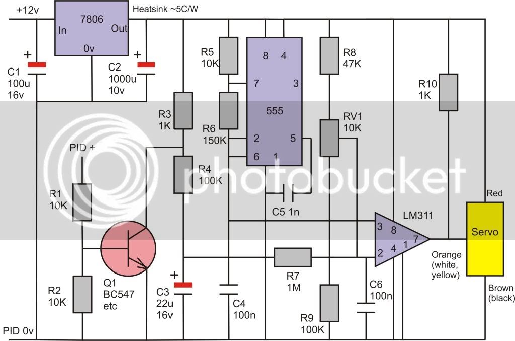
This is a basic "start point" circuit - it will not be fully practical as it stands:

Q1 averages the digital drive pulses to give an analogue equivalent at the LM311 pin 2.
The 555 produces a ramp with a period of 20msec.
The LM311 produces pulses with an on time dependant on the PID output.
As I have said elsewhere, this servo control and the PID controller function are crying out for an Arduino. The libraries are readily available and will require a limited amount of modification and integration to produce a complete controller.
The temperature controller for the HLT could then be added to complete the project.
None of this is relevant if you are looking at solenoid driven valves!
Please note - this does not include finished detailed circuits, it is a few ideas for those who know a bit of electronics. I have made something along these lines but have not fully tested or toleranced the design.
The easiest way to achieve a variable flow is with motorised valves - there are many examples including central heating.
The cheapest way to implement a motorised valve is with an off-the-shelf servo, typically used in Radio Controlled models. It contains the motor and gears at a fraction of the individual part cost.
The simplest way to control this servo is by removing part of the case and connecting directly to the motor. The drive from the PID makes the motor run in one direction for "hotter" and the other for "cooler" (some form of current limiting will be needed). However the method shown here does not involve taking the servo apart and would suit any similar servo with sufficient stall torque.
The outputs from a standard inexpensive eBay PID (TET612, N2006P) include a relay with normally open and normally closed contacts or a Solid State Relay drive of 8V open circuit and 40mA short circuit.
In this case I have chosen to use the SSR output. It can be set to have a maximum repetition rate of 2 seconds and the time it is "on" is determined by the heat requirement of the system.
This is not directly compatible with an off-the-shelf servo mechanism:
Taken from: http://en.wikipedia.org/wiki/Servomechanism -
"The servo expects a pulse every 20 ms in order to gain correct information about the angle. The width of the servo pulse dictates the range of the servo's angular motion.
A servo pulse of 1.5 ms width will typically set the servo to its "neutral" position or 45°, a pulse of 1.25 ms could set it to 0° and a pulse of 1.75 ms to 90°."
The interface will therefore need to convert a comparatively slow on/off signal into a 50Hz rectangular signal.
The MG955 servo used here seems to be widely available and is considered to be one of the worst on the market - however, it is very cheap and adequate for this application.
e.g. http://cgi.ebay.co.uk/ws/eBayISAPI.dll? ... AQ:GB:1123
http://www.rcmodelreviews.com/chineseservos1.shtml
This is a basic "start point" circuit - it will not be fully practical as it stands:

Q1 averages the digital drive pulses to give an analogue equivalent at the LM311 pin 2.
The 555 produces a ramp with a period of 20msec.
The LM311 produces pulses with an on time dependant on the PID output.
As I have said elsewhere, this servo control and the PID controller function are crying out for an Arduino. The libraries are readily available and will require a limited amount of modification and integration to produce a complete controller.
The temperature controller for the HLT could then be added to complete the project.


