Wire STC1000 direct to fridge ??

The Homebrew Forum

Help Support The Homebrew Forum:

This site may earn a commission from merchant affiliate links, including eBay, Amazon, and others.

loady

[Superlative Сasual Dating Real Women]
Joined
Apr 7, 2012
Messages
482
Reaction score
13
Location
GB
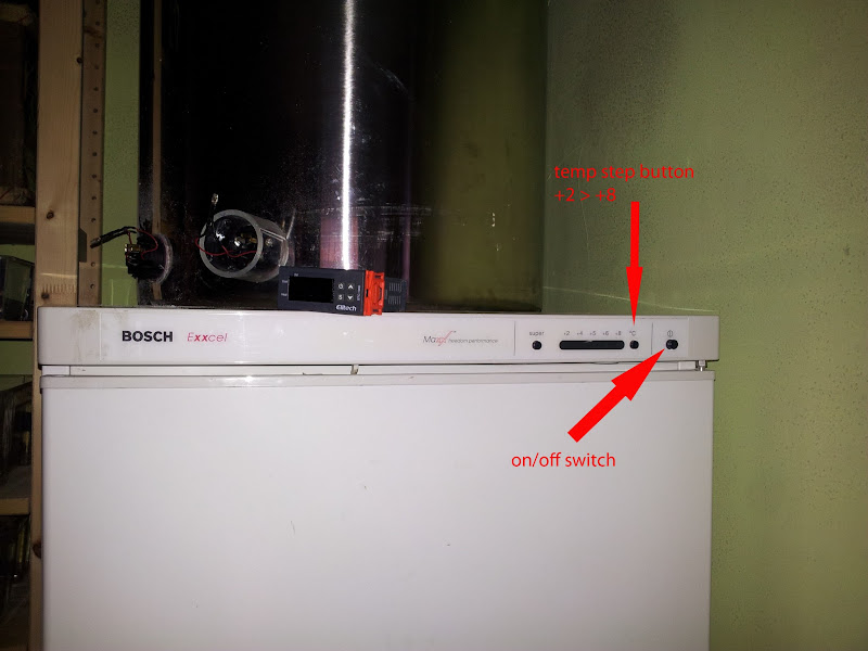
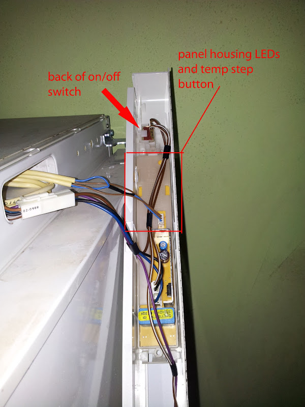
I have a tall larder fridge which i have designs to be a kegerator, i fancy mounting the stc into the front panel, can this be done by wiring it directly to the on off switch ? thus eliminating the need to trail the fridges plug to the STC in a box ?..also could the tube heater somehow be wired the same way using the fridges supply, given it is only 60watt ?
20130228_171133.jpg

20130228_171159.jpg
 
I don't see why you couldn't simply plumb the fridge switch wires into the cold switch of the STC controller. As for using the fridge supply for the heater... hmmm not so sure. Are you saying you want to take power for it from the fridge? If so, it'd have to be on the live side of the fridge switch. Don't forget your STC will also need power.
 
yes, thats what i am saying..forgot the STC needs power as well but i dont think it needs that much ?...could i just not split the live from the fridge switch or would i be drawing to much from it ??
 
I'm not an electrician but neither the STC nor tube heater will draw much current.
 
Is there enough space in the front panel for the STC and wiring? You don't want it to get really crampt in there if everything is going to be wired together.

As for your query I don't see any issues with what you plan. You could run all 3 off the fridge supply and use the switch you have pointed out above wired into the cool circuit as mentioned previously.

Would be a really neat install but just be sure that everything gets enough space/ventilation.
 
Yes you can, ive done it with mine, but its a compressor on top job which made it very easy..Which was lucky cos i used a BIG ATC800+ controller :)

Just take a bit of time sussing all the wires you have there :)


if you have room to squeeze in a strip of leggo type connector in behind the controller that will save trying to attach 3 or more wires to the controller terminals at once, which can be tricky with shortgrub screws, but can be done more easily with a crimped on rings

if the fridge has a fan look into wirring that so it runs all the time and not just when the chilling is on, otherwise look into adding a fan to blow over the pipe heater and move the air about. i used a 12v pcfan again cos of the roomy top compressor compartment stashing the 12v transformer wasnt a problem.. But with a long enough trailing lead you could easily attach a 12v transformer to the fridge rear out of sight with velcro tape or something.

have fun..
 
Yes you can mate. Work out what your live and neutral wire to the board are an the other one will be the feed to the compressor. The 3 that go in the top if the board from your picture are just the sensors from what I can make out. Yes you can just use the fridge supply for the heater. It will only either work on heating or cooling at different times so the 13 amp plug top will be fine for what you need
 
I have about a foot of free space that you can't see behind the panel, the stc will protrude slightly and i have plenty of room for connectors, i also have crimping tools, the only problem is, electronically, i am just a hobbiest and have a multimeter, how do i use it to find which wires are what and where they go?
 
Can you run another 3 core wire in behind the panel down the back of the fridge? If so it should be reasonably straight forward.

You should be able to tell from the colour of the wires, down at the compressor, which one is which. What you want to do is look to see where the plug wire goes to, you want to splice into this part of the wire to get your "always on" power. You run this (all 3 wires) to the back of where the STC-1000 is. From here you spit the positive cable between the STC-1000 positive and the heater switched positive on the STC-1000. The negative gets split to the STC-1000 negative and what will be the heater negative. The earth simply gets added to the connector block so that it can be joined to the heater cable. Next you get the length of cable required in order to feed back down to your heater. The positive goes into the other side of the STC-1000 switched positive, the negative goes into the split negative on the connector block and the earth goes onto the split earth on the connector block. This cable is then run down to where you want the heater by whatever the neatest method is to get it there. Simply wire it up to the heater correctly and the tricky wiring is done. For the fridge switch simply take the wires off the switch that's currently there and put them into the "cool" switch on the STC-1000.

Easy as pie eh ;)
 
the wires going from the circuit board will already be going to the compressor. you just need to disconnect the circiut board as you will be using the stc1000 to control the compressor.
 
gibb58 said:
the wires going from the circuit board will already be going to the compressor. you just need to disconnect the circiut board as you will be using the stc1000 to control the compressor.

I doubt it'll be that easy though. The "circuit board" will be connected by thin gauge wire to the relay/starter. This circuit won't be made for any sort of current draw, I wouldn't think. This is where you need to be REALLY careful as this is how fires start.
 
gibb58 said:
the wires going from the circuit board will already be going to the compressor. you just need to disconnect the circiut board as you will be using the stc1000 to control the compressor.

This is what i was hoping to do....but having just read...

I doubt it'll be that easy though. The "circuit board" will be connected by thin gauge wire to the relay/starter. This circuit won't be made for any sort of current draw, I wouldn't think. This is where you need to be REALLY careful as this is how fires start.

Maybe Scott is right, though i have to say the writes in the panel look to be the same as the wire inside the 3 core...is there a way to test if i am overloading it ?...the electrics in my shed are part p and rcd etc.
 
loady said:
gibb58 said:
the wires going from the circuit board will already be going to the compressor. you just need to disconnect the circiut board as you will be using the stc1000 to control the compressor.

This is what i was hoping to do....but having just read...

I doubt it'll be that easy though. The "circuit board" will be connected by thin gauge wire to the relay/starter. This circuit won't be made for any sort of current draw, I wouldn't think. This is where you need to be REALLY careful as this is how fires start.

Maybe Scott is right, though i have to say the writes in the panel look to be the same as the wire inside the 3 core...is there a way to test if i am overloading it ?...the electrics in my shed are part p and rcd etc.

Without knowing the gauge and rating of the wire used, plus whether it splits or goes through any other circuits etc, then no. You also have to be aware of the relays etc that these wires will be connected through. Although the rating of the actuation part of the relay will be fine, the rating of the switch circuit will be extremely low.

I honestly wouldn't advise doing it, I'm covering myself right here as saying I wouldn't recommend it in the slightest :)

It won't take much work to do a "proper job" anyway, 1 length of 3 core wire, a 10mm hole in the top rear of the panel and the job's a goodun :)
 
Sound sense Scott !... Why cut corners, i have the 3 core and it will still look the Bollocksa well.. So, if i follow your advice from previous post I'm good to go ?... Can i visually identify the wires or will i need to test with multimeter ?
 
loady said:
Sound sense Scott !... Why cut corners, i have the 3 core and it will still look the Bollocksa well.. So, if i follow your advice from previous post I'm good to go ?... Can i visually identify the wires or will i need to test with multimeter ?

I'm fairly certain you will be able to visually identify them, often better safe than sorry though so a multimeter will take all guesswork out of the equation.

I would simply follow where the power plug terminates at, hopefully there would be a way to splice into that area, preferably by screw/ring terminal. If you can't then I would look at splicing in with some decent connector block or a small junction box... dealers choice :D

I definitely wouldn't go any further than the plug/cable as messing with anything after the compressor is just asking for trouble.

The cable for the plug is always going to be brown/blue/green & yellow, if it's not something's very wrong :D
 
ScottM said:
gibb58 said:
the wires going from the circuit board will already be going to the compressor. you just need to disconnect the circiut board as you will be using the stc1000 to control the compressor.

I doubt it'll be that easy though. The "circuit board" will be connected by thin gauge wire to the relay/starter. This circuit won't be made for any sort of current draw, I wouldn't think. This is where you need to be REALLY careful as this is how fires start.

In the light of recent news stories, perhaps Bosch appliances don't need any help catching fire!

I don't know why I'm jesting, I've got a Bosch dishwasher (not the dodgy one in the report, though), fridge freezer and washing machine :pray:

I'd be tempted just to drill a hole or two and run it externally like I've done with the STC 1000, though I haven't got the fridge yet! left socket to cool, right socket to heat...
STC1000Project.jpg
 
morethanworts said:
ScottM said:
gibb58 said:
the wires going from the circuit board will already be going to the compressor. you just need to disconnect the circiut board as you will be using the stc1000 to control the compressor.

I doubt it'll be that easy though. The "circuit board" will be connected by thin gauge wire to the relay/starter. This circuit won't be made for any sort of current draw, I wouldn't think. This is where you need to be REALLY careful as this is how fires start.

In the light of recent news stories, perhaps Bosch appliances don't need any help catching fire!

I don't know why I'm jesting, I've got a Bosch dishwasher (not the dodgy one in the report, though), fridge freezer and washing machine :pray:

I'd be tempted just to drill a hole or two and run it externally like I've done with the STC 1000, though I haven't got the fridge yet! left socket to cool, right socket to heat...

Wiring it like I've said is effectively the same. The only additional load will be on the socket, plug and cable. Nothing will be going into any components in the fridge itself. The cable, socket and plug will be absolutely fine to handle the extra quarter amp required :)
 
ScottM said:
gibb58 said:
the wires going from the circuit board will already be going to the compressor. you just need to disconnect the circiut board as you will be using the stc1000 to control the compressor.

I doubt it'll be that easy though. The "circuit board" will be connected by thin gauge wire to the relay/starter. This circuit won't be made for any sort of current draw, I wouldn't think. This is where you need to be REALLY careful as this is how fires start.
The circuit board has a live neutral an switched live to it. Just chuck the old circuit board away and put the live and neutral to the supply of the stc, link the live across to the common on your stc and put your switched wire onto the comp terminal. It's a domestic fridge believe me they aren't that complicated when you get past all the wired hanging about
 
gibb58 said:
ScottM said:
gibb58 said:
the wires going from the circuit board will already be going to the compressor. you just need to disconnect the circiut board as you will be using the stc1000 to control the compressor.

I doubt it'll be that easy though. The "circuit board" will be connected by thin gauge wire to the relay/starter. This circuit won't be made for any sort of current draw, I wouldn't think. This is where you need to be REALLY careful as this is how fires start.
The circuit board has a live neutral an switched live to it. Just chuck the old circuit board away and put the live and neutral to the supply of the stc, link the live across to the common on your stc and put your switched wire onto the comp terminal. It's a domestic fridge believe me they aren't that complicated when you get past all the wired hanging about

They aren't complicated at all, but the wiring system at the controller side of things isn't rated for any current. Just because you can pull a live, neutral and earth wire out of the setup doesn't mean that you can draw any current, safely, from it.

It's a risk, why take the risk?
 
Back
Top