PID Build Complete (almost) with a few Pics.

The Homebrew Forum

Help Support The Homebrew Forum:

This site may earn a commission from merchant affiliate links, including eBay, Amazon, and others.

AndyBWood

Regular.
Joined
Feb 25, 2012
Messages
231
Reaction score
1
Location
Exotic Manchester
Evening All,

First off, thanks for everyone’s input on this; as always, much appreciated. :thumb:

Finally put this together at the weekend; it took a while but, to honest, once I had all the bits& bobs in front of me it was pretty straightforward.
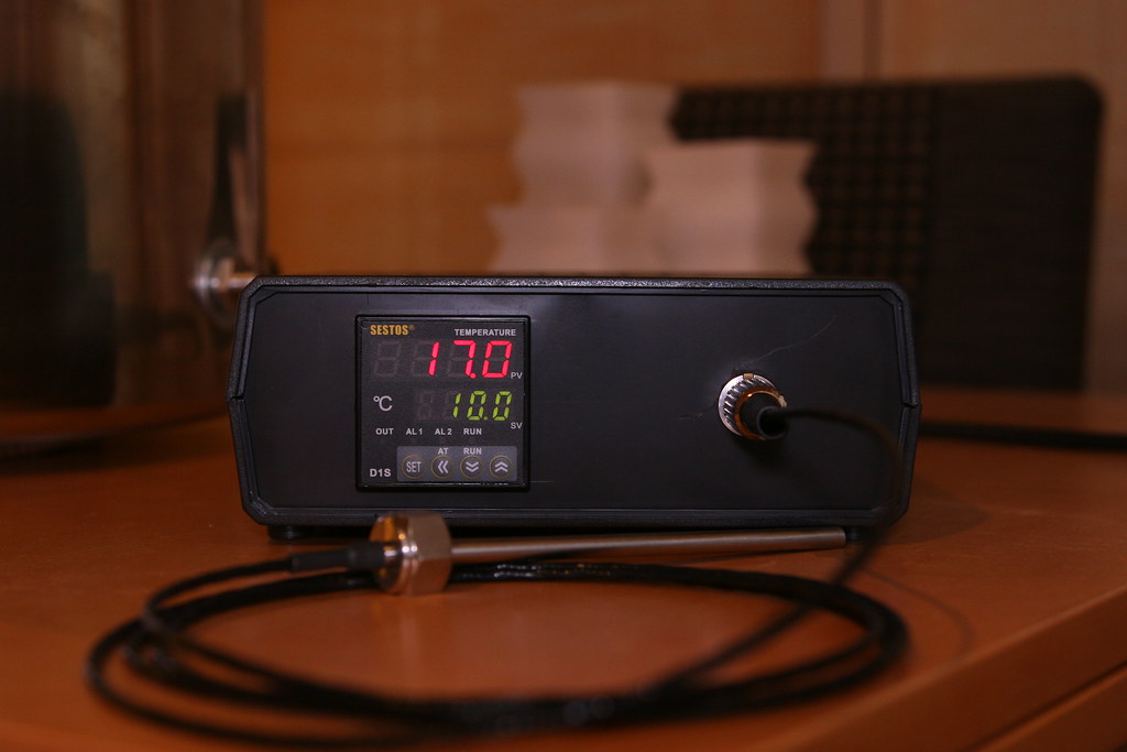

8569731122_ba2ea79a3f_b.jpg


By far the hardest task was cutting the reception holes for the PID, sensor and power leads but Dremell and Stanley Knife came into their own. I had a few ‘wonderings’ with said items and a couple of scars remain ( the box not me ! ) but that’s being hyper critical. Overall, it went well.

I used a 3 pin DIN plug to connect the sensor which was a bit of a pain. Unfortunately, I’d already ordered this before reading the XLR suggestions which, as a bulkier component, would probably have been far easier.
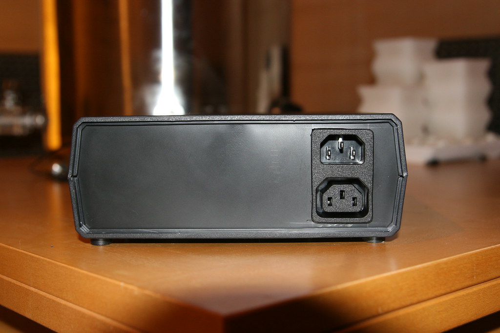

8568638551_a204bbd971_b.jpg


Round the back I used a combined in / out socket which keeps things as tidy as possible.

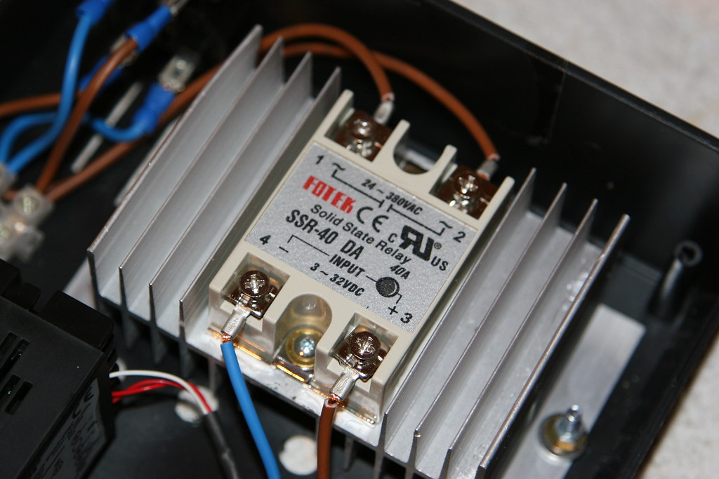
Inside, its pretty straightforward. Again taking onboard the consensus, I shelved the plans to install some type of fan. Having run the PID solid for a good hour the heatsink seems to cope well enough. I did, however, drill a good handful of extra holes in the base of the box to encourage more airflow.
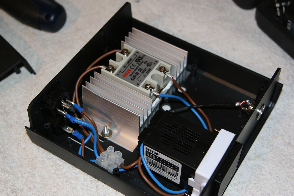

8568655183_ee85df93ef_b.jpg


Seems to work fine. I also used a good smear of heatsink compound where the SSR seats; the kind of paste used on computer CPUs.

8568652443_2ac3edefcb_b.jpg


One thing lacking at the moment is a 3 amp fuse in line with the PID itself which I’ll attend to this week.

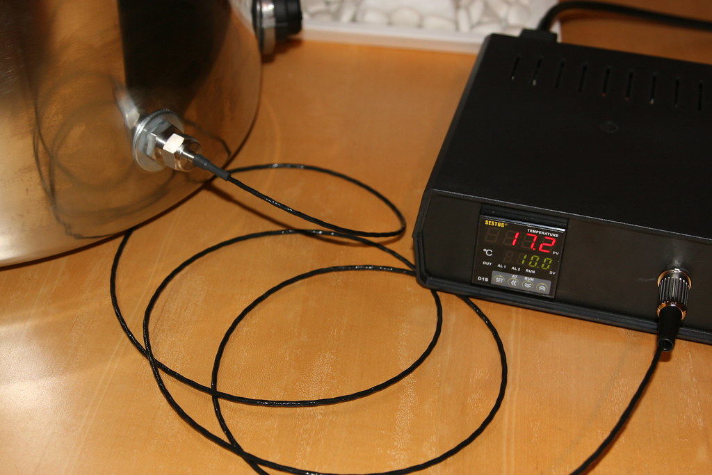
After letting the PID autotune with around 35 litres of water at 85 degrees it seems to hold the temp around +/- 0.2 degrees of target which, for my sparging purposes is, I hope, accurate enough. I might have a tinker with the parameters to see if I can get closer; just for fun mind…..


8569740360_1f126a9647_b.jpg


So the weekend beckons, AG2 and, maybe, Worthington White Shield. I’m sure building the PID won’t help me make better beer but HLT temp is now just one less thing to worry about plus a real sense of satisfaction having put something like this together.

Thanks again for all the help. :thumb:

Andy
 
Hi EV,

Probably doesn't show up well in the pics but there's a long line of vents in the box, top and bottom, plus I popped a lot of extra 10mm holes directly under the heatsink as well. The box is also raised up on rubber feet so I'm hoping it'll be ok :pray:

I will keep my eye on it but take on board your point; thanks. Do you think having a 40amp relay and only running less than 10amps makes a difference ? ie - PID pretty relaxed ? Is does seem to run pretty cool.

Cheers - If needs be I can always go to MK 2 now I know what I'm doing !

A
 
Very nice job...one i am looking to do, a parts list would be very nice, i will also be looking to xlr connections..also just out of interest i assume that probe is in a thermo well ? can you document that please..looks very neat and would go well as an all in one build project for myself and many others here. As i said very interested a parts list for the PID and thermowell :thumb:
 
Hi Loady,

I'll try to put together the parts I bought if it would help but maybe Wednesday / Thursday before I get chance.

Cheers :cheers:

A
 
No problem, I look forward to it.
 
AndyBWood said:
Do you think having a 40amp relay and only running less than 10amps makes a difference ?
Heating effect is heating effect, you cannot get away from amps X amps X resistance.
Your acid test will heating your HLT.
I'm confident you will have no problems. :thumb:
 
Andy, what type of fitting is the one that the temp probe goes through and into the boiler ?
 
Evening All,

As requested here goes with a list of bits n bobs I bought to assemble the PID; nearly everything came via ebay :

Project Box

PID

40amp SSR

Heatsink

In/Out Combined Power Socket

PT100

Thermopocket

My Thermopocket thread is here

3 Pole DIN Socket

3 Pole DIN Plug

Heatsink Compound

Other Stuff

15amp Terminal Block from B&Q
All the wiring was striped out of 13amp flex
The crimp on wiring connectors / eyelets came from Maplins

I think that’s it; apologies if I’ve missed anything
 
Well done Andy..a great help and inspiration to me and others no doubt !! :cheers: my next project after the first AG brew
 
Paultr,

What I really like about the project box is that the front and back panels are removable which makes it a lot easier to cut out the holes required, etc.

The plastic material was also really easy to cut and drill. For me, this was still the hardest part to get right but being able to take the panels out made the task as easy as it could be .

Cheers

A
 
Good job! :thumb: What are you using this one for, HLT? Would I need two SSRs and heatsinks to power two kettle elements (ie: for my copper)?
 
Hi TDM,

My PID will be used for the HLT and will run one element.

When getting up to temp both HLT elements will be on ( for speed ) but only one powered via the PID / SSR. The other will be plugged directly into the wall.

Once approxiametely up to temp I will turn off the directly powered element and maintain temp using just the one via the PID.

I don't see any reason why you couldn't power 2 elements via one SSR as long as the current draw does not exceed what the SSR is designed to handle. My SSR is rated at 40amp.

I'm no electrician though : whilst I'm pretty sure how this would be wired up I would feel far happier if one of more experieneced members came forward with an answer for you. Wouldn't want to give you unqualified ( not to mention potentially dangerous ) advice.

If no one comes back with an answer I'd suggest you post up the question as a seperate query. To be honest, I'd be interested to know if my thoughts are sound as well.

Cheers and Good Luck with your build. :thumb:

A
 
+1 for that...im guessing you would just another in/out and join the wires on the inside to the SSR ?
 
AndyBWood said:
Paultr,

What I really like about the project box is that the front and back panels are removable which makes it a lot easier to cut out the holes required, etc.

The plastic material was also really easy to cut and drill. For me, this was still the hardest part to get right but being able to take the panels out made the task as easy as it could be .

Cheers

A
Sounds really good - going to get one :thumb:
 
AndyBWood said:
Evening All,

First off, thanks for everyone’s input on this; as always, much appreciated. :thumb:

Finally put this together at the weekend; it took a while but, to honest, once I had all the bits& bobs in front of me it was pretty straightforward.


8569731122_ba2ea79a3f_b.jpg


By far the hardest task was cutting the reception holes for the PID, sensor and power leads but Dremell and Stanley Knife came into their own. I had a few ‘wonderings’ with said items and a couple of scars remain ( the box not me ! ) but that’s being hyper critical. Overall, it went well.

I used a 3 pin DIN plug to connect the sensor which was a bit of a pain. Unfortunately, I’d already ordered this before reading the XLR suggestions which, as a bulkier component, would probably have been far easier.


8568638551_a204bbd971_b.jpg


Round the back I used a combined in / out socket which keeps things as tidy as possible.

Inside, its pretty straightforward. Again taking onboard the consensus, I shelved the plans to install some type of fan. Having run the PID solid for a good hour the heatsink seems to cope well enough. I did, however, drill a good handful of extra holes in the base of the box to encourage more airflow.


8568655183_ee85df93ef_b.jpg


Seems to work fine. I also used a good smear of heatsink compound where the SSR seats; the kind of paste used on computer CPUs.


8568652443_2ac3edefcb_b.jpg


One thing lacking at the moment is a 3 amp fuse in line with the PID itself which I’ll attend to this week.

After letting the PID autotune with around 35 litres of water at 85 degrees it seems to hold the temp around +/- 0.2 degrees of target which, for my sparging purposes is, I hope, accurate enough. I might have a tinker with the parameters to see if I can get closer; just for fun mind…..


8569740360_1f126a9647_b.jpg


So the weekend beckons, AG2 and, maybe, Worthington White Shield. I’m sure building the PID won’t help me make better beer but HLT temp is now just one less thing to worry about plus a real sense of satisfaction having put something like this together.

Thanks again for all the help. :thumb:

Andy

Andy,

First class build. I'm doing similar after being inspired by yours. Do you have a wiring diagram for this by any chance.
 
That is a very tidy build Andy

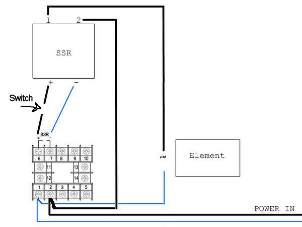
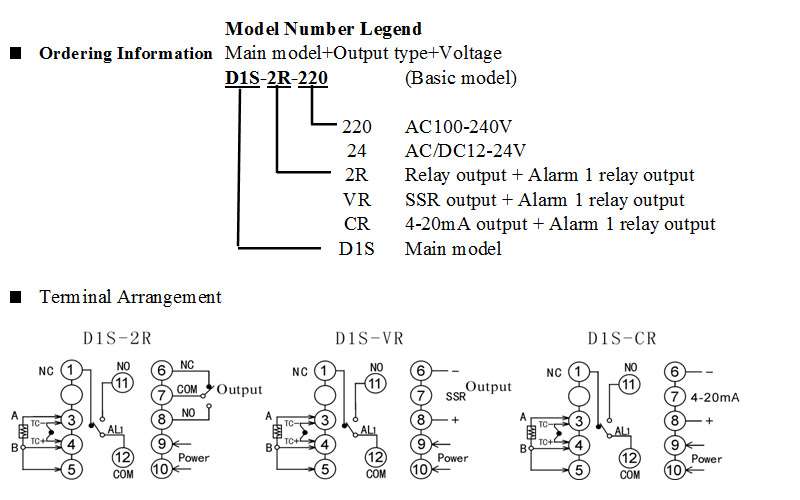
Here a basic wiring diagram for an Auberins PID. For a Sestos it is just the terminals numbers that are changed. We would use the D1S-VR for SSR output.
It is very simple and you can ignore the switch as that is only if you need a manual overide.

8888834703_a85d04a146_z.jpg


d1s-info.jpg
 
I've just been reading this post to look for a suitable pid, however the link for the one that you used has expired. DO you possibly have a fresh link?
 
Back
Top