Boiler Automation Electrical Advice Required

The Homebrew Forum

Help Support The Homebrew Forum:

This site may earn a commission from merchant affiliate links, including eBay, Amazon, and others.
MyPIN PID ordered and a solar pump, I plan to use the solar pump to draw wort from the area at the bottom of the boiler where the element sits and return it to the top of the boiler throughout the mash process circulating the wort, I will sit the PT100 sensor in the return pipe thus ensuring constant flow over the grain and temperatures hopefully maintained better throughout. I don't have everything laid out as yet but once it's in place I will post some pictures.
 
Smiley you may need a tap from output of pump into vessel so you can slow pump down or a pwm motor control from Ebay, I use both. I found my pump ran two fast and with thick mash could either run dry or just collapse pipes. My set up is Biab but with a basket to hold bag in a 50 litre vessel, if I pump too hard wort runs over basket and I run risk of pump clog a hop filter helps stop this eventuality as does tap and pwm.
Also bear in mind with sensor where mine is , unless your pump is running temp reading is poor, I am going to fit second sensor in wall of vessel for boil and cooling temps.
Its a learning curve and even if it goes haywire, you still get beer at the end of a brewday!
 
I found my pump ran two fast and with thick mash could either run dry or just collapse pipes.

Thanks for the advice, I tend to mash at full brew lengths (or as close as I can get with my setup) so the wort generally is not too thick, but like you say its a learning curve and we always end up with beer.
 
Hi donchiquon, I used one of these http://www.ebay.co.uk/sch/sis.html?...h+Detachable+Connector&_trksid=p2047675.m4100 I use a three wire sensor so has compensation for ambient temps, I also use a 40A SSR to drive a 3kw element, yes the heat sink gets hot and i am going to use a small 12v fan. The limitation with temp sensor in T piece from tap is with big grain bill when recirculation slows the temp takes time to adjust. The SSR may get replaced with resistor variable one to lower voltage to element, 3kw is a little high for rolling boil, more control is better.


Thanks @stpete. Looks like a good piece of kit. I'm not sure it is compatible with my inkbird but I might just buy a new PID and box it all up with the variable voltage adjuster/dimmer. It sounds from your post like I could use this instead of an SSR...
 
MyPIN PID ordered and a solar pump, I plan to use the solar pump to draw wort from the area at the bottom of the boiler where the element sits and return it to the top of the boiler throughout the mash process circulating the wort, I will sit the PT100 sensor in the return pipe thus ensuring constant flow over the grain and temperatures hopefully maintained better throughout. I don't have everything laid out as yet but once it's in place I will post some pictures.


Hi @Smileyr8. I think I'll be joining you in this as soon as I finish a kegerator build. I'm going to order @stpete's PID and temp sensor.

Are you going to use an SSD with the PID or a dimmer/variable voltage thingy?

Have you decided where and how you will fit the temperature probe?
 
Hi!
An SSR is essentially a switch, turning the element on and off, which isn't good for the element. A variable voltage device would be better, but I don't know how to wire one into a PID.
 
Are you going to use an SSD with the PID or a dimmer/variable voltage thingy?

Have you decided where and how you will fit the temperature probe?

Hi Donchiquon,

I plan to use the PID with a SSR and a PT100 sensor, currently I am thinking of making a stand out of copper pipe this will double as the flow from the boiler, the pump will draw the wort to the surface I will then add the sensor to the return pipe via tee compression fitting with a blanking plug at the sensor end, I am hoping that the circulation of the wort will normalise the temperatures throughout the boiler.

Its all in the planning phases at the moment so things could change, also the build will need to fit around other household projects that are going on.
 
Guys however you choose to control your elements you will need some form of SSR, the Pid controllers cannot switch or control the 10 or more Amps that a 2.4kw or 3kw element can draw, if you are using a resistor to vary the voltage this is done in conjunction with an SSR or a pwm. A relay is really needed the allow you to swicth the high currents. These setups can draw very lethal amounts of electricity, if ya not sure please get it checked.
 
Got my PID and SSR off Inkbird, but no heat sink (apparently the warehouse made an error). The K sensor that came with it isn't going to be much use because:
1. I can't find any fittings that will allow me to reduce 1/2" BSP to 1/16" thread.
2. It isn't watertight.
3. the sensor isn't long enough.
So, I've ordered a model with 1/4" thread and 5cm sensor. Inkbird said they'd send me a heat sink, am awaiting delivery (they said they'd send it but haven't confirmed it's been sent :rolleyes: ).
So, frustratingly, I can't use the thing properly until I get the heat sink but I've wired it up and used for as long as I dare and seems OK.
 
Notice:
R: RELAY; S: SSR; N: None
RNR model represents the main control is RELAY, with only 1 alarm(RELAY).
SSR model represents the main control is SSR, with 2 alarms(SSR and RELAY).

So you want the TA4-SSR version...

OK so I have ordered the wrong one "RNR", can't I use this with a SSR?
 
Thanks @Fil! All ordered! :thumb:

Any idea what spec of SSR will I need to pair it with to control a 1600W element? Is this the right flavour?

http://www.ebay.co.uk/itm/Solid-Sta...320536?hash=item4affb03f58:g:X04AAOSw1h5XQWiZ

Thanks!

That looks like the 25a SSRS i use to control elements upto 3kw.
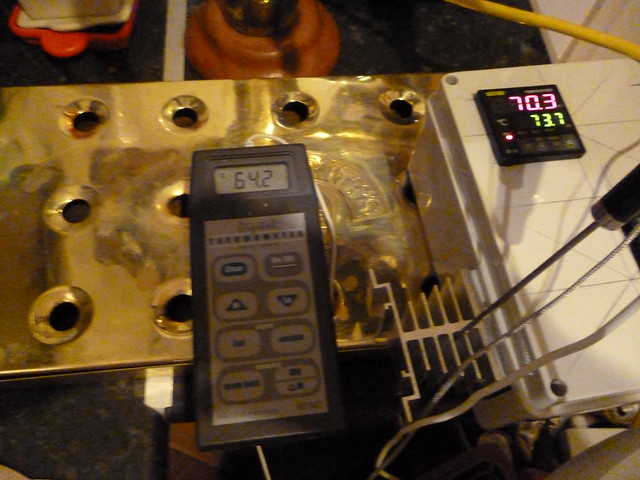
However when running with 3kw elements i have measured temps over 60C on the 3rd vane down from the heatsink so would suggest you mount the heatsink externally to the box rather than internally, or build a fan into it too.

8440023604_bb6254ec12_z.jpg


other folk recommend the 40a versions? I spotted that after buying mine..
they should run cooler

mounting externally involves cutting /forming/drilling a couple of lugs to fix under the heads of the screws used to clamp to the heatsink which can then be slotted or fixed against the case interior ;) i used a bit of split and opened/flattened 15mm copper tube, easy to bend cut file and drill and wont interfere with the earthing of the baseplate/heatsink.
 
Notice:
R: RELAY; S: SSR; N: None
RNR model represents the main control is RELAY, with only 1 alarm(RELAY).
SSR model represents the main control is SSR, with 2 alarms(SSR and RELAY).


OK so I have ordered the wrong one "RNR", can't I use this with a SSR?


the relay model simply closes the contacts between the 2 control terminals,
the ssr model will provide a dc drive current to power the ssr on when needed.


A relay model can be used to control an ssr if you either use a 2ndary dc voltage power supply(battery? phone charger) to control the ssr and use the pid relay terminals to turn it on/off.the other option is to open the pid and find a couple of solderpads to draw a dc voltage from. me i would probably use a hi mah rechargable battery :)
 
Still not had an update from ink bird regarding controlling a 5.5kw element off a 30amp supply.


For the dial up/down control either the resistance controlled ssr option i suggested or the PWM controller option suggested by donchiquon on page 3 of this thread will work, though with a a 5.5kw element i would opt for a 40/60a ssr
 
That looks like the 25a SSRS i use to control elements upto 3kw.

However when running with 3kw elements i have measured temps over 60C on the 3rd vane down from the heatsink so would suggest you mount the heatsink externally to the box rather than internally, or build a fan into it too.


8440023604_bb6254ec12_z.jpg


other folk recommend the 40a versions? I spotted that after buying mine..

they should run cooler


mounting externally involves cutting /forming/drilling a couple of lugs to fix under the heads of the screws used to clamp to the heatsink which can then be slotted or fixed against the case interior ;) i used a bit of split and opened/flattened 15mm copper tube, easy to bend cut file and drill and wont interfere with the earthing of the baseplate/heatsink.


Perfect - found this one which sounds like the 40a version

http://m.ebay.co.uk/itm/262446610611?_mwBanner=1

Thanks again!
 
Perfect - found this one which sounds like the 40a version

http://m.ebay.co.uk/itm/262446610611?_mwBanner=1

Thanks again!

Not for pid use, that is for control with a variable resistor, not a dc voltage
s-l225.jpg

http://www.ebay.co.uk/itm/24V-380V-...021254?hash=item1c55599fc6:g:ZvYAAOSwgQ9V1D9T

is the sort of thing you want, if you squint at the pic you will see a + and - marked on the control terminals (3 n 4) indicating DC voltage control while the one you linked to has a zigzag+ arrow symbol between the control terminals

add a 500k pot to the ssr you linked to and you have a dial up and down power controller ;)
 

Latest posts

Back
Top